| [Top: John S. Allen's Home Page] [Up: bicycling articles] |
|
| [Top: John S. Allen's Home Page] [Up: bicycling articles] |
|
Parts and MaterialsI used an ordinary 6-foot (183 cm) long, ¼ inch (6.35 mm) diameter glass fiber safety flag pole (about $5 at K-Mart) and #20 rubber-insulated zip cord pulled apart into single-conductor insulated strips. Rubber insulation is preferable to plastic insulation, which tends to hold kinks. The wrap is white vinyl electrical tape. Achieve a neat wrap by adhering one end of a 25-inch (60 cm) length of tape to a doorknob to tension the tape while rolling it up on the flagpole. Keep the wire parallel to the flagpole to achieve a teardrop-shaped aerodynamic profile with the antenna wire at the trailing edge. It is possible to push the wire from side to side under the tape to correct the alignment. DimensionsI tuned the antenna at an unused repeater input frequency near 146.25 MHz, halfway between the 144.51 and 147.99 MHz frequency limits of 2 meter FM operation. The SWR is below 1.2 over this entire range. The final dimensions for the tuned antenna are:
Amateurs outside North America will want to increase these dimensions by about 1%, since their 2-meter band centers at 145 MHz. Tuning and wrappingDo tune your J-pole, rather than simply using my measurements. The shortening effect of the flagpole and tape can vary somewhat. Start with each section a few percent long. Since the tape affects the tuning, you must wrap each section of the antenna before tuning it. First, slip the flag off the flagpole and attach the dipole section starting at the top of the pole, using a few short, temporary pieces of tape, then wrap the dipole from end to end, except for an inch or so (3 cm) at the center, where you will have to get at the wire for tuning. If you will use a dip meter, you need only leave access to the lower end of the dipole for later connection of the matching stub. Wrapping tape. One end of the tape is stuck
to a doorknob
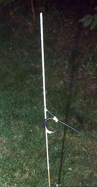
But to use an SWR meter as I did, cut the dipole apart at the exposed access point in its middle. Solder a coax feed cable to each leg of the dipole and cover the inch of exposed wire at the bottom end of the dipole with a short wrap of tape. Plant the bottom of the flagpole in the ground and run the feedline off horizontally to avoid interaction with the dipole. Test the SWR, unwrap and trim each end of the dipole, rewrap and test again until SWR is lowest at 146.25 MHz. Removing only 1/8 inch (3 mm) from each end of the dipole will raise the resonance by about 1 MHz, so work slowly and carefully.
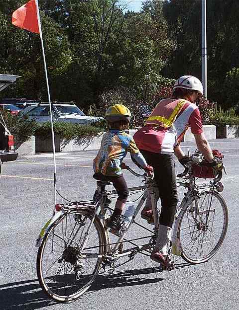
Remove the insulation at the feedpoint. Solder the feedline to the feedpoint, attaching the center conductor of the coaxial cable to the longer leg of the "J." Route the feedline down the pole opposite the side where the matching stub passes around the pole. Test for SWR again, trimming the bottom end of the matching stub 1/16 inch (1.5 mm) at a time, soldering its cut ends together and trying adjustments to the feed point height after each trim. The matching stub makes it possible in theory to achieve a perfect 1.0 SWR at one frequency: the length of the stub adjusts mostly reactive impedance, and the feedpoint position adjusts mostly resistive impedance. In theory, a J-pole fed by an unbalanced coaxial cable should be equipped with a balun at the feedpoint. You could loop a few turns of the feed cable at the antenna end into a coil balun if you wish, or slip a ferrite bead over the feedline. With careful tuning, this J-pole can perform satisfactorily -- though with less favorable directivity -- in the 70-cm band. Extra tape near the ends of the dipole and top of the matching stub will increase capacitive loading at all three of the antenna's voltage maxima at 2 meters, but only three of the seven at 70 cm, bringing the 3rd harmonic into the needed frequency range. For easy-on, easy-off mounting, remove the steel mounting plate from the bottom of the pole. Flatten one end of a 1-foot length of 3/8 inch automotive brake line tubing to support the bottom of the flagpole. Two small worm-gear hose clamps will attach the tubing to the vertical strut of a bicycle's baggage rack. Sandpaper or file the bottom of the flagpole into a wedge shape to orient the antenna aerodynamically, with the dipole wire at the rear. The antenna as installed on the author's home-built tandem.
|
| [Top: John S. Allen's Home Page] [Up: bicycling articles] |
Contents © 1999 John S. Allen Last revised 2 February 2003 |
 An article in the January 1999 Bicycle Mobile Hams
of America Newsletter, by Jim Varney, ham call sign AE6N, describes an antenna for the
2-meter band, made by sliding coax insulator braid over a glass fiber bicycle safety flag
pole. I took a slightly different approach, building a J-pole antenna by taping wire to
the safety-flag pole. My antenna is a bit more aerodynamic, though tuning it is trickier.
An article in the January 1999 Bicycle Mobile Hams
of America Newsletter, by Jim Varney, ham call sign AE6N, describes an antenna for the
2-meter band, made by sliding coax insulator braid over a glass fiber bicycle safety flag
pole. I took a slightly different approach, building a J-pole antenna by taping wire to
the safety-flag pole. My antenna is a bit more aerodynamic, though tuning it is trickier.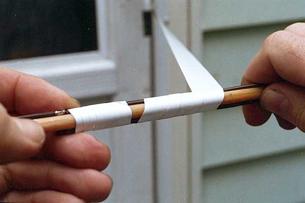
 When the dipole is tuned, remove
the feedline, solder the center of the dipole back together and tape over it. Also solder
one end of the matching stub to the bottom end of the dipole. Extend half of the matching
stub wire's length down the flagpole, then pass it around the pole and extend the rest up
the opposite side. Then tape everything except for three inches at the bottom of the
matching stub..
When the dipole is tuned, remove
the feedline, solder the center of the dipole back together and tape over it. Also solder
one end of the matching stub to the bottom end of the dipole. Extend half of the matching
stub wire's length down the flagpole, then pass it around the pole and extend the rest up
the opposite side. Then tape everything except for three inches at the bottom of the
matching stub..